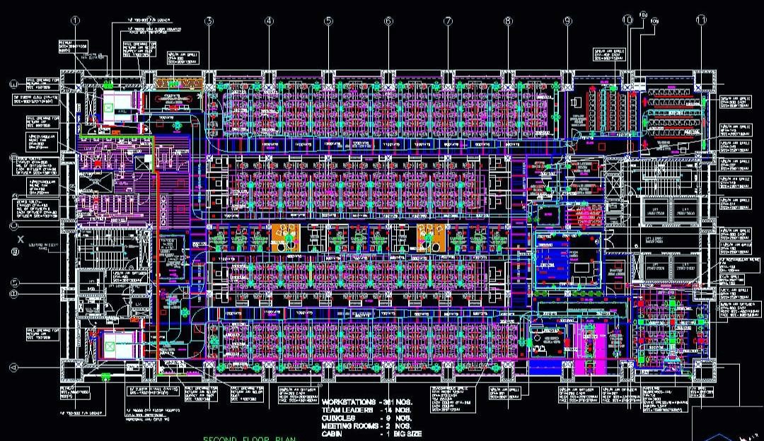
Duct Designing in AUTOCAD
Duct designing in AutoCAD involves creating detailed plans and layouts for HVAC (Heating, Ventilation, and Air Conditioning) ductwork systems using the AutoCAD software. AutoCAD is a powerful computer-aided design (CAD) tool widely used by engineers, architects, and professionals in various industries to create precise and accurate drawings.
Here are the general steps involved in duct designing using AutoCAD:
-
Gather Information: The first step is to gather all the necessary information related to the HVAC system, including building layout, dimensions, HVAC load calculations, and requirements for the ductwork.
-
Set Up the Drawing: Open AutoCAD and create a new drawing file. Set up the drawing units and scales based on the project requirements.
-
Draw Building Layout: Draw the building layout in the AutoCAD file, including walls, partitions, doors, and windows. This will provide the context for placing the HVAC ductwork.
-
Design the Ductwork: Based on the HVAC design specifications, start drawing the ductwork routes. Use AutoCAD's line, polyline, and other drawing tools to create the ducts in the correct dimensions and configurations.
-
Add Fittings and Accessories: Incorporate fittings such as elbows, tees, reducers, dampers, and grilles into the duct layout. These fittings are essential for ensuring proper airflow and distribution.
-
Label and Annotate: Provide clear labels and annotations for the ducts, fittings, and other components to make the drawing easily understandable for installation and fabrication purposes.
-
Create Sections and Elevations: Utilize AutoCAD's section and elevation tools to generate detailed views of the duct system, helping visualize how the ducts run through walls, floors, and ceilings.
-
Check for Interferences: Review the duct design for any clashes or interferences with other building elements, such as structural members or electrical conduits. Adjust the duct layout if required to avoid conflicts.
-
Prepare Documentation: Generate a comprehensive set of ductwork drawings, including plans, sections, elevations, and details, to be used during construction and installation.
-
Coordinate with Other Disciplines: Collaborate with other professionals involved in the building project, such as mechanical engineers, architects, and structural engineers, to ensure proper coordination and integration of the ductwork within the overall building design.
Duct designing in AutoCAD requires a good understanding of HVAC principles and design standards. Precise and accurate drawings are essential to ensure the successful installation and functioning of the HVAC system in the building.